PDF chapter test TRY NOW
In the previous section, we have done an activity to prove that the electric current through a metallic conductor produces a magnetic field around it.
But, What defines the pattern of the magnetic field produced by a current through a conductor?
Does the pattern of the magnetic field depend on the shape of the conductor?
In this session, We shall examine this with an activity.
Initially, we shall first consider the pattern of the magnetic field around a straight conductor carrying current.
Steps:
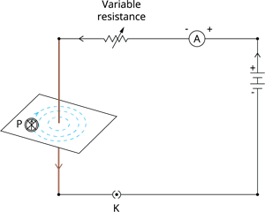
The following are the components required to do this activity - Battery (12\ V), Variable resistance (or a rheostat), Ammeter (0–5\ A), Plug key, and long straight & thick copper wire.
- Insert the thick copper wire through the centre and normal to the plane of rectangular cardboard. Make sure that the cardboard is stationary and does not slide up or down.
- Join the copper wire vertically between points X and Y, as shown in the below figure, in series with the battery, a plug and key.

- Spray some iron filings evenly on the cardboard. (You may use a salt sprinkler to spray.)
- Maintain the variable of the rheostat at a fixed position and record the current through the ammeter.
- Close the key. So that a current flows through the copper wire. Ensure that the copper wire placed between points X and Y remain vertically straight.
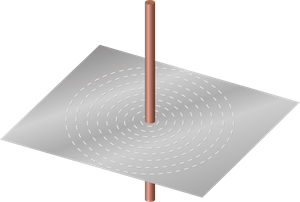
- Tap the cardboard mildly a few times. Note the pattern of the iron filings. You would notice that the iron filings align themselves, showing a pattern of concentric circles around the copper wire (See the below figure).

A close up of the pattern obtained
Observations:
- What do these concentric circles express?
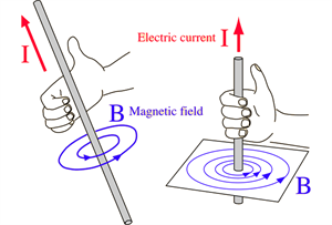
The concentric circles represent the magnetic field lines. The arrows in the circles show the direction of the field lines.
- How to find the direction of the magnetic field?
Locate a compass at a point (P) over a circle. Note the direction of the needle. The direction of the compass needle's north pole would provide the direction of the field lines produced by the electric current through the straight wire at point P. Directions are shown by an arrow.

- Does the direction of magnetic field lines get reversed if the current direction through the straight copper wire is reversed?
Yes. You will see that now the needle moves in the opposite direction, It means that the direction of the magnetic field produced by the electric current is also reversed.
- What happens to the compass needle deflection located at a given point if the current in the wire is changed?
To examine this, vary the current in the wire. We observe that the deflection in the needle also changes.
If the current in the circuit is increased, the deflection also increases. It shows that the magnitude of the magnetic field created at a particular point increases as the current through the conducting wire increases.
-
What results in the needle deflection if the compass is moved away from the copper wire, but the current through the wire remains the same?
To examine this, now place the compass at a farther point from the copper wire (say at point Q).
- What difference do you witness?
We observe that the deflection in the needle decreases. Thus, the magnetic field produced by a given current in the conductor decreases as its distance increases.
From the figure, You can notice that the concentric circles representing the magnetic field around a current-carrying straight wire become larger and larger as we move away from it.
