PUMPA - SMART LEARNING
எங்கள் ஆசிரியர்களுடன் 1-ஆன்-1 ஆலோசனை நேரத்தைப் பெறுங்கள். டாப்பர் ஆவதற்கு நாங்கள் பயிற்சி அளிப்போம்
Book Free DemoThe screw gauge works on the principle that when a screw rotates in a nut, the distance travelled by the tip of the screw is directly proportional to the number of rotations.
Pitch of the screw:
The pitch of the screw is the distance travelled by the tip of the screw for one complete rotation of the head. It is equal to 1 mm in conventional screw gauges.
The least count of a screw gauge:
The distance moved by the tip of the screw for a rotation of one division on the head scale is called the least count of a screw gauge.
Zero Error of a screw gauge:
When the movable stud of the screw and the opposite fixed stud on the frame area are brought into contact, if the zero of the head scale coincides with the pitch scale axis, there is no zero error.
Positive zero error:
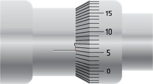
When the adjustable stud of the screw and the opposite fixed stud on the frame area are brought into contact, the zero error is positive if the zero of the head scale lies below the pitch scale axis.
When the adjustable stud of the screw and the opposite fixed stud on the frame area are brought into contact, the zero error is positive if the zero of the head scale lies below the pitch scale axis.

Positive zero error
The above figure shows the positive zero error. Here, the 4th division of the head scale coincides with the pitch scale axis.
Then the zero error is positive. And, it is given by
Z.E = + (n × LC)
Where ‘n’ is the head scale coincidence
In this case,
Zero error = + (5 × 0.01) = 0.04 mm.
So, the zero correction is – 0.05 mm.
Negative zero error:
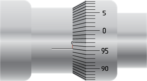
When the plane surface of the screw and the opposite plane stud on the frame area are brought into contact, if the zero of the head scale lies above the pitch scale axis, then the zero error is negative.

Negative zero error
The above figure shows the negative zero error. Here, the 96th division coincides with the pitch scale axis. Then the zero error is negative.
And, it is given by,
ZE = – (100 – n) × LC
ZE = – (100 – 95) × LC
= – 5 × 0.01
= – 0.05 mm
The zero correction is + 0.05 mm.
The below table represents how the thickness of the objects are measured using a screw gauge.
|
No. of
Observations
|
Pitch Scale Reading
(N) mm
|
Head Scale Reading
No of circular divisions on reference line
(n)
|
Head Scale Reading
Value
(n * LC) mm
|
Total Reading
Observed
(DO = N +n)
mm
|
Total Reading
Observed
Corrected
D = DO + ZE
mm
|
|
1
|
|
|
|
|
|
|
2
|
|
|
|
|
|
|
3
|